When I switched career paths from IT to software engineering, there was one downside. I stopped working on computer networks in a professional capacity, which is a topic I’ve always been very passionate about. Fortunately, I’ve been able to work on some exciting networking challenges at my software engineering job.
My organization started a biannual event where we all meet in person and work on software together as a global team. This scenario involves hundreds of heavy internet users in a giant room who demand a lot out of their web connection! After soliciting bids from several network providers, we realized that buying the equipment and running it ourselves could be significantly cheaper than renting the equipment from a networking contractor. Since then, we’ve successfully run the event together multiple times.
This video about my team’s event gives a quick overview of the networking challenges we overcame:
Network requirements
Running a temporary network in a large space presented some interesting challenges. When I designed this network, I had to consider the following factors:
- How to configure the wireless network to support 1000+ clients from across the spectrum of possible devices (phones, laptops, IoT devices, etc.).
- How to effectively balance traffic while still delivering 10 Gbps of bandwidth to most of the equipment (and at least 1 Gbps everywhere).
- How to deal with attenuation of copper cable over longer distances at a 10 Gbps transfer rate.
- How to mitigate the impact of marine radar being used at a nearby naval port on our wifi network.
- How to transport our equipment safely and quickly.
- How to organize our equipment effectively for rapid deployment.
- How to prepare and educate our installation and removal teams for accurate deployment.
I also designed a companion wireless popup network. For more information on how we deployed the wireless network, see the follow-up blog post, Building a wireless pop-up event network.
Venue challenges
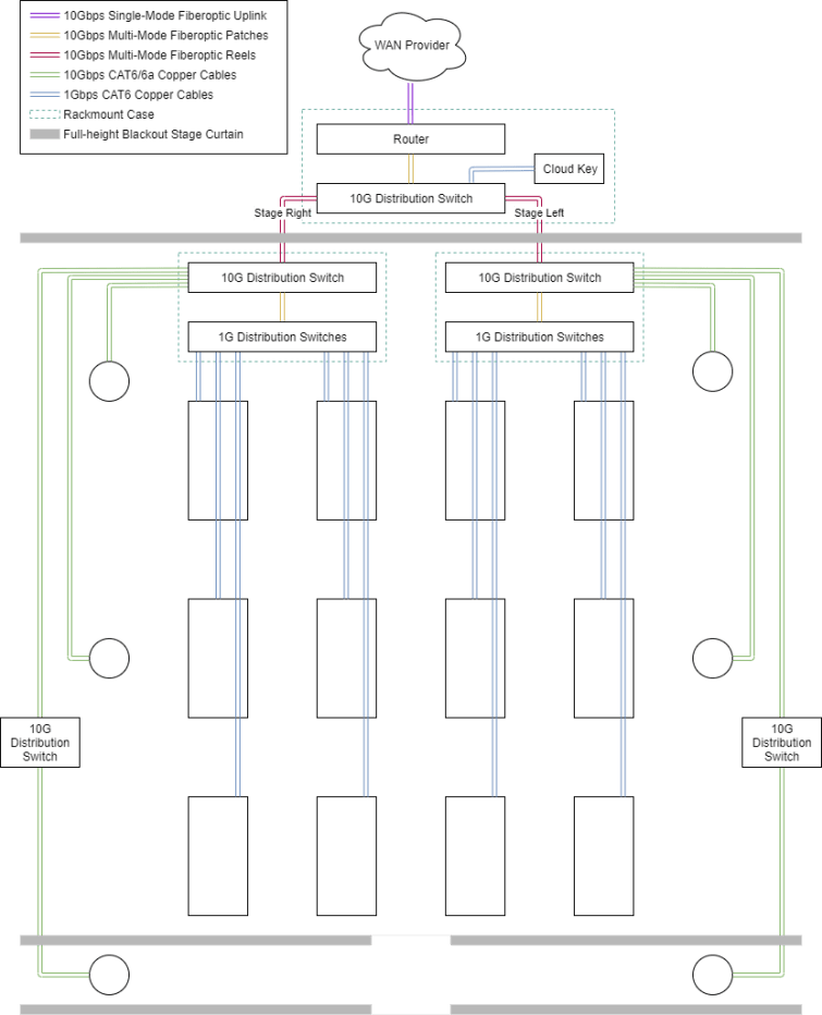
The venue we were at was WaMu Theater in Seattle. The theater is a concrete and steel building with a 7,000-person capacity. The main area is divided by a set of floor-to-ceiling blackout stage curtains to form a “wall,” which creates a large room and a smaller lobby area. In the large room, there’s a stage area and another curtain separating the large room from backstage.

In the large area, we needed to fit around 70 large tables and chairs to seat 600 people. This setup meant we had to run cables between rows of tables, where people would be walking. We needed to minimize the number of interwoven cables by only running them in one direction. This way, we could create paths for our crew to use when driving utility vehicles around the venue, so we didn’t run over data wiring.
We had to provide as much of the 10 Gbps uplink as possible to our users, since they expected a lot out of their network connections (both wired and wireless). Since users generally did not have a 10 Gbps capable NIC, we only had to prioritize providing as close to 1 Gbps as possible to client devices.
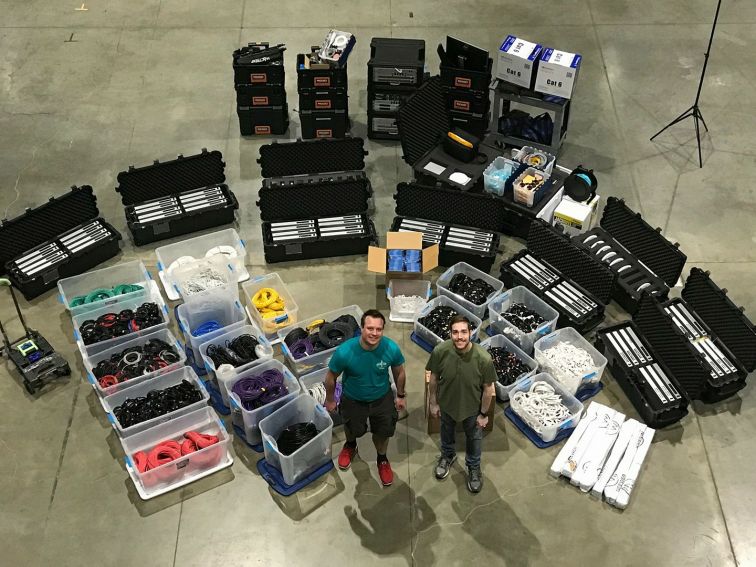
In addition to these technical hurdles, we also had to innovate a solution for organizing, tracking, and transporting the equipment safely to the venue and back again. We needed to optimize deployment and teardown of the equipment, because it allowed us to quickly parallelize our activities.
Equipment choices
When I decided how to conquer our venue challenges and network requirements, I decided to use Ubiquiti’s UniFi line of devices. I went with UniFi in part because of the price of the equipment. However, I also chose UniFi because its software-defined network approach would allow us to create extensive automation to help us set up and run our network.
One of the most overlooked parts of doing a pop-up network deployment is the importance of safe transportation and tracking of devices. In our setup, we have over 100 network devices to deploy, most of which are packed in Pelican 1740 cases with custom foam.
A few weeks prior to the event, we pull all of our equipment and update firmware on them by setting up a minimal core infrastructure and plugging in sets of devices for maintenance. This serves three purposes; verifying the hardware is still functional, updating the firmware on the device, and ensuring the UniFi controller tracks the device. This helps reduce the time of rollout from device configuration provisioning.
When it comes to packing the switches which sit on each team’s table, each case contains 8 switches and 8 power cables, and is labeled with its numeric subset on the outside. When we configure these, we sequentially name the switches “S001”, “S002”, etc. and label the cases “S001-S008”, for example. When placing them on the tables, we line up the table number with the switch number to make debugging problems and tracing anomalies easier.
For access points, each case contains a combination of models; UAP-AC-SHD, UAP-AC-HD, and UAP-AC-Pro. In past years we have built out the wireless network using these devices, but we are currently using XG BaseStations and XG APs, which helps to significantly reduce the number of devices needed to cover the environment. Because we power most of our AP hardware from Power Over Ethernet switches, we do not need to carry PoE injectors for each access point.

Cables are sorted by length and type and wrapped with electrical tape to keep the cables in shape while stored. These are counted ahead of time when putting together the map; each table needs to have a measurement from it to the distribution satellite core to which it needs to connect. This also helps speed up the rollout by prescriptively choosing cables for specific parts of the row.
Wired networking
Basic network design
The wired network has to serve two purposes; to route traffic for users sitting at each table, and to route traffic for the wireless access points. That means keeping the network link speed at 10 Gbps up to the distribution switches, which then connect to a switch on each table at 1 Gbps. Since we were using 10 Gbps-capable wireless access points, we also had to make sure those were wired in accordingly; we could not run an access point from any of the wires run to the rows of table switches, as that would only have a data rate of 1 Gbps.
To balance traffic, I split the room into a left and right side. All of the tables on either side were connected to that side’s distribution switch through CAT6 at 1 Gbps. Those distribution switches were connected to a 10 G distribution switch by multi-mode fiber. That 10 G distribution switch connects to the access points and, through a couple long reels of cable, to the router.
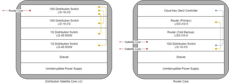
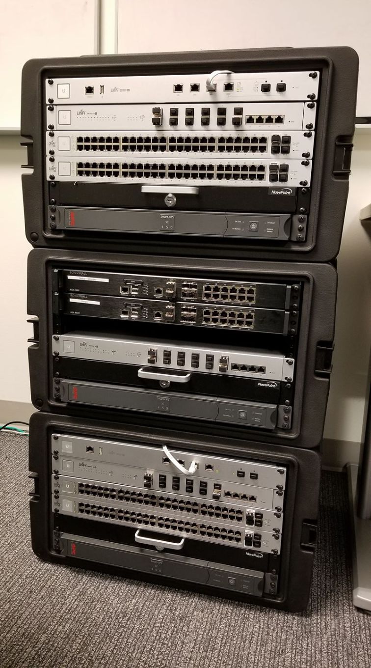
The core 10 Gbps infrastructure is assembled in three rolling rack-mount audio cases, each of which has a rack cooling fan in the rear to handle the high heat of having several network devices in close proximity. To help with mobility of these heavy boxes, each one has a sturdy handle, roller wheels, and lock-on side caps with a TSA-compliant lock; they can also stack securely. In each of the three racks, in addition to the network equipment, we have a utility drawer and UPS to provide battery backup in the event of a brownout as well as to provide clean power to the devices. The drawer is handy for holding fiberoptic cable plugs (which protect the ends of the cable), SFP rubber plugs, extra MM fiber, etc.
The two distribution satellite cores in our current design have 2 10 G distribution switches; one acts as the backbone of the rack, and one hosts the wireless access points. These two devices can be converged to one with no loss of bandwidth. To facilitate 70+ switches, 2 48-port switches are in each to distribute the load, linking to the tables at 1 Gbps.
The router core has primary and cold backup routers, which, through moving a microSD card with backup configurations from one device to another, can be manually “failed over” to. The router core links to each of the two distribution satellite cores through reels of long multi-mode aqua fiber.
The router core also has a Cloud Key Gen2, which is used to manage all of the UniFi devices deployed into the environment and provide analytics. This device has a 10 minute battery backup and can easily handle the 1000 or so client devices we need.
Measuring maximum cable distance
One key aspect of the physical design that needs to be taken into account at the beginning is maximum distance of any single cable. All cable types have a maximum operating distance before attenuation (when a cable’s electrical connection is too weak/inconsistent to hold a data link).
For devices connected with multi-mode fiberoptic cables, this is 600m (2000ft).
For devices connected with CAT6 cables, it’s 10 Gbps at ~37-55m (~120-180ft) or 1 Gbps at 100m (~330ft), depending on cable quality.
For devices connected with CAT6a cables, we can push 10 Gbps at 100m (~330ft).
Using cables longer than these recommended distances can cause signal degradation, assuming a link is even possible. For this reason, in our design, we had to use US-16-XG switches as “repeaters” to transmit 10 Gbps through copper wire, as we only had CAT6 cable available at the time.
Power over Ethernet (PoE)
I mentioned before that our access points use Power Over Ethernet (PoE). PoE is a standard which allows for the injection of DC power either from a compatible switch or a dedicated PoE injector box. This allows us to run access points in places which do not have to have a power outlet nearby. Our UniFi access points are all PoE; the XG BaseStation access points do not run from the switches, however, and require their own dedicated (higher amperage) injector, which ships with the device.

Adding a wireless network
While this post explains how we deployed a pop-up network with wired-only clients, we also added a high-capacity, high-throughput, low-latency wireless network to the wired network infrastructure. See how we achieved this in my follow-up blog post, Building a wireless pop-up event network.
Have you been thinking about doing a similar pop-up wired event network? If you’ve already done one, what challenges have you faced and overcome?

One thought on “Building a wired pop-up event network”